Case Study #202: Using a Strip Heater in a Foil Stamping Process
Home > Blog Archive > Category: Case Studies > Case Study #202: Using a Strip Heater in a Foil Stamping Process
Case Study #202
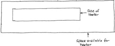
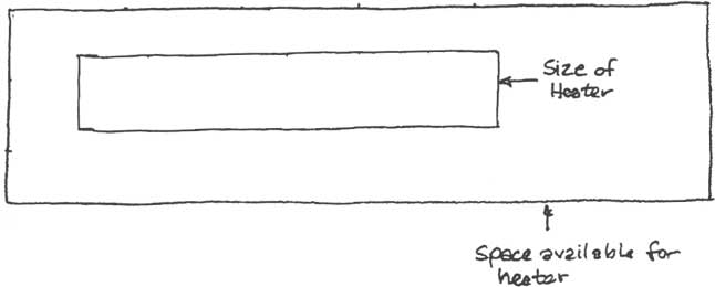
We had a customer once that had been using a strip heater, similar to our configuration 022, in a foil stamping process. The heater measured 6” long, 1-1/8” wide, 150W at 120V, and had two holes in it— each 1/4” in diameter spaced 4” apart on the centerline of the heater. The heater fit in a 10” x 2-3/4” space. The customer asked for a quote from us and when we quoted it, our configurator alerted us with a note warning high watt density. The customer ordered 4 pieces of this heater. He thought these heaters would work for his process that required it to reach 400°F; however, the heaters only allowed his process to reach 300°F.
What Happened?
Both the original heaters and the newer heaters were rated for 150W at 120V. What was the difference that caused this result? The Thermal Corporation tech sheet had recommended a wattage of 115W.
The industry standard for strip heaters specifies the wattage tolerance as +5, -10%. The tolerance does not specify as ± x% because from a safety standpoint it is safer to have a lower limit on how hot the heater can get. +10% of a specified wattage will often lead to premature heater failure and can cause damage to the customer’s process.
Wattage is determined using the following formula:
![]()
Considering the bi-lateral tolerance on wattage, it is possible to get a 15% variance in wattage between the two heaters and both could be in spec.
This is usually not a problem because, under normal circumstances, the heaters would be within a control loop. The temperature controller adjusts the amount of heat provided to produce the desired temperature.
To measure wattage it is easier to measure the resistance, BUT you must remember a couple of things:
(1) When first heating up the resistance of the heater will increase about 4% or so. (Heating anneals the wire/ribbon removing the work hardening which was added to the wire in the drawing and forming process.)
(2) When the heater cools down, the resistance will be about 2% higher than before it was initially heated up.
This is how the 4% breaks down: 2% is due to removing the work hardening.
The other 2% is due to the resistance of the NiCr wire increasing with temperature.
Look at it this way…
Resistance happens when the current (electrons) run into other electrons. If the temperature rises, then non-current electrons are moving around more than before and are sort of “getting in the way” of the current electrons to a slight degree. The higher the temperature is, the more the non-current electrons get in the way.
We, at Thermal Corporation, design our heaters to produce the target wattage (and resistance) when the heater is hot. NOT ALL MANUFACTURERS DO THIS!
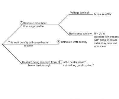
What about the high-watt density warning? This warning means the heater could result in decreased heater life. Could the heater be made larger? Could we also raise the wattage, if desired?
One of our engineers, Kyle Otte, has an answer to this: “Yes, making the heater larger will allow for more total wattage while also lowering the watt density thus removing the high-watt density alert. This will yield more even heating over the entire space as well as more total energy into the process with the added benefit of greater heater life.”

Written by Jim Dixon and Shelby Reece
Edited by Kyle Otte
Date Published: 06.07.2019
Last Updated: 09.03.2019

